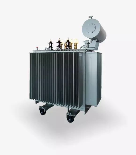
Special Oil-Immersed Distribution Transformers SPHERA DT
HV-Side Switchable Transformers
These transformers are designed to be switchable for two different rated network voltages. The voltage change is possible in an off-circuit state, using a tap selector head located on the cover. The insulation of a switchable transformer is selected for the higher of the rated voltages. The most commonly used switchable voltages are: 20 kV / 15 kV; 20 kV / 10 kV; 15 kV / 10 kV.
Earthing Transformers
Earthing transformers combine the functions of distribution transformers and neutral point earthing for medium-voltage (MV) networks. The LV winding – 400 V or 420 V – is intended for supplying the auxiliary needs of the transformer station.
The HV winding is usually designed in a zig-zag connection. The power rating of the HV winding is the sum of the distribution power transferred from HV to LV and the power associated with the zero-sequence current flowing from the neutral point of the HV winding to the earthing system.
The neutral point of the HV winding is usually connected to earth through a reactor (or resistor). The reactor (or resistor) limits the zero-sequence current to the required value. The zero-sequence current flows through the reactor only under single-phase-to-earth fault conditions in the MV network. Therefore, the transformer and the reactor are designed for a limited duty time; this time can be specified in seconds, minutes, or hours.
The earthing transformer and the reactor are usually designed as two separate units, but in some designs, the reactor and the transformer are placed in the same tank. This solution is used in the case of multi-point earthing of the MV network using several earthing transformers.
Rectifier Transformers
These transformers are used to supply rectifier or converter systems. They feature a specially designed electromagnetic circuit and reinforced insulation system tailored for this purpose. These transformers are designed in close cooperation with the Customer, as the design depends on the type of rectifier/converter system and the nature of the load. Each transformer design takes into account the magnitude of current harmonics flowing in the windings and the associated increased heat generated in the windings.
Transformers with Additional Taps on the LV Side
These are two-winding transformers with additional taps on the LV winding. This system can only be used when the secondary winding is connected in star. Such transformers have two rated secondary voltages. When the transformer operates at the lower LV voltage (on taps), its power rating may be equal to the full winding power or it may be limited. At the manufacturer’s test station, each pair of windings: HV – full LV voltage and HV – LV tap voltage is tested separately, and 2 test certificates are provided with the transformer.
Three-Winding Transformers
These are transformers that have 3 windings – one HV winding and two LV windings, galvanically separated. Such transformers are most commonly used in solar farms or for traction power supply.
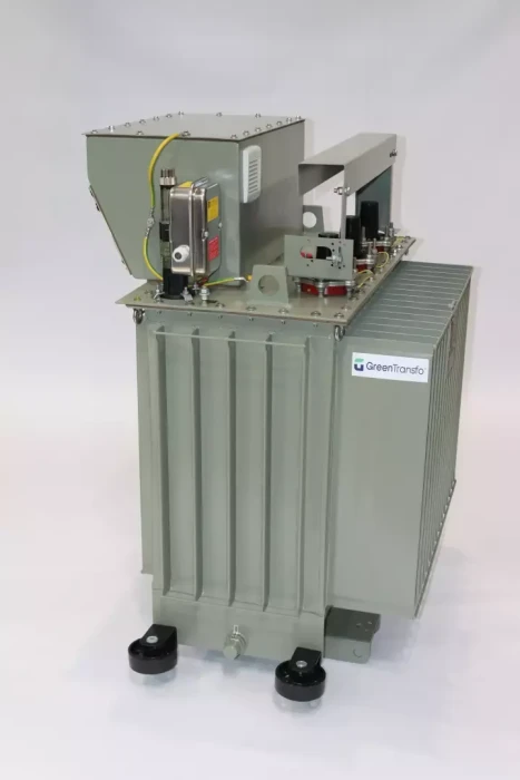
Self-Protected Transformers
These transformers automatically disconnect from the MV network in the event of any internal fault. They are equipped with 2 or 3 medium-voltage fuses, a disconnector, and a system detecting abnormal increases in pressure or temperature, oil level drop, or internal short circuit. Upon operation of the protection, the transformer is disconnected from the network while the MV line remains energized. The transformers are built according to the IEC 60676-13 standard.